Students can Download 1st PUC Electronics Model Question Paper 4 with Answers, Karnataka 1st PUC Electronics Model Question Papers with Answers helps you to revise the complete syllabus.
Karnataka 1st PUC Electronics Model Question Paper 4 with Answers
Time: 3.15 Hours
Max Marks: 70
Note :
- The question paper contains four parts.
- Part-A is compulsory, Part-D contains two subparts (a) problems (b) essay-type questions.
- Explanation without circuit diagram, wherever necessary, does not carry mark.
PART-A
Answer all questions. Each question carries one mark. (10 × 1 = 10)
Question 1.
How many electrons supplied to a neutral conductor make it to be charged to -IC?
Answer:
n = 6.25 × 10¹⁸ electrons.
Question 2.
Write an equation for specific of cylindrical conductor in terms of radius.
Answer:
ρ = \(\frac{\pi r^{2} R}{4 L}\)
Question 3.
What is the significance of the time constant of the LR series circuit?
Answer:
Its significance is about 63.3% of the maximum current will be reached in the circuit in this time during growth.
Or
63 .3% current will be decreased in this time during decay.
Question 4.
What type of extrinsic semiconductor will be obtained when Indium impurity is added to Germanium semiconductor?
Answer:
P-type
![]()
Question 5.
What is the reason for choosing silicon over Germanium semiconductors?
Answer:
Leakage current is less or more abundant or less costly or temperature withstanding capacity is more.
Question 6.
Which region of the transistor is moderately doped?
Answer:
Collector.
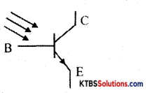
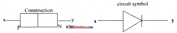
Question 7.
Draw the circuit symbol of the phototransistor.
Answer:
Question 8.
What is an OR gate?
Answer:
OR gate is a logic gate that can have two or more inputs one output will be in a high state when one or more inputs are in the high state. Or gate is a logic gate that can have two or more inputs one output, the output will be in a low state when all the inputs are in a low state.
Question 9.
Write the Boolean expression for the output Y of the gate shown.

Answer:
Y = \(\overline{\mathrm{AB}}\)
Question 10.
What makes the charge move from one conductor to another?
Answer:
The potential difference.
PART-B
Answer any five questions. Each question carries two marks. (5 × 2 = 10)
Question 11.
Mention the uses Sphygmomanometer, Glucometer, Pulse oximeter, and Digital Thermometer.
Answer:
- Sphygmomanometer- used to measure blood pressure,
- Glucometer- to measure the glucose level in the blood,
- Pulse oximeter- to measure hemoglobin content in the human body,
- Digital thermometer- to measure the temperature of the human body.
Question 12.
Briefly explain the determination of the frequency of an AC using RO.
Answer:
Display an AC signal on the screen. The length of one wave or distance between two consecutive crests (peaks) or troughs is measured in terms of main division by displaying one complete wave on the screen using the time/div control unit.
Then time period of the wave (T) =length of one wave x (time/division), frequency (f) = 1/T.
![]()
Question 13.
Draw the circuit diagram of the RC high pass filter. Write an expression for its cut-off frequency.
Answer:
Circuit diagram

fc = \(\frac{1}{2 \pi \mathrm{RC}}\)
Question 14.
What are the factors on which the width of the depletion layer depends?
Answer:
Types of material, doping level, temperature, and type of biasing.
The phenomenon of abrupt increase in the current through pn junction under reverse bias due to an increase in the kinetic energy of minority charge carriers is called avalanche break down.
Question 15.
Current gain β of a transistor is 100. Its base current is 20μA. Calculate and IE of the transistor.
Answer:
α = \(\frac{\beta}{1+\beta}=\frac{100}{1+100}\) = 0.990099 ≈ 0.99
Ic = βIB = 100 × 20 × 10-6 = 2mA;
IE = Ic + IB = 2mA + 20μA = 2.02mA
Question 16.
What is an optocoupler? Draw its circuit.
Answer:
Optocoupler is an electronic device that interconnects two electrical circuits by means of an optical interface.

Question 17.
What is the need for 2’s complement method of subtraction? Mention any two advantages of digital technology.
Answer:
- The necessity of using 2’s complement method is to reduce circuit complexity.
- Advantages of digital technology: It is cheap, easily replaceable, requires less space, less affected by noise & temperature, It has memory. It has greater accuracy & precision. It can be programmed. Any two are to be written.
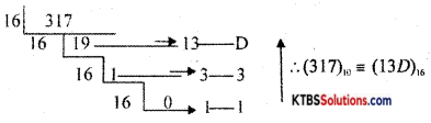
Question 18.
Convert (317)10 into equivalent hexadecimal numbers.
Answer:
PART-C
Answer any five questions. Each question carries three marks. (5 × 3 = 15)
Question 19.
Explain the role of Electrics in the day to day life.
Answer:
Explanation of the role of electrics.
Question 20.
State and explain Kirchhofrs voltage law.
Answer:
KVL: Algebraic sum of voltages in a loop of an electrical network is zero. Or in a loop of an electrical network algebraic sum, EMFs in different branches is equal to the algebraic sum of IR drops in different branches of the same loop.
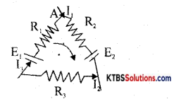
Applying KVL – E1 + E2 = I1R1 – I2R2 + I3R3
Question 21.
Calculate I3 and R3 in the following circuit.
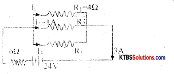
Answer:
Main current, I = 3 A& supplied voltage, V = 24V.
Voltage across 6Ω is = 3 × 6 = 24V. Voltage across parallel combination,
V2 = V – V1 = 6V
V2 = I1R1 = I2R2 = I3R3
So I1 = V2/R, = 1.5 A
I = I1 + I2 + I3
So I3 = I – I1 – I2 = 0.54;
R3 = V2/I3 = 12Ω
![]()
Question 22.
What is the principle of a parallel plate capacitor? Briefly explain the construction of electrolytic capacitors.
Answer:
Bringing an uncharged identical plate parallel to a charged plate, the potential between the plates decreases. Decrease in potential increases the capacitance of the arrangement. Condition.
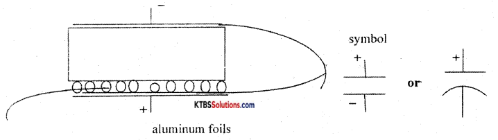
It consists of two thin aluminum foils. On one of the foils, borax or phosphate, or carbonate (electrolyte) is coated. On which absorbent paper or plastic gauge is placed. Over which second A1 for I is placed. Then rolled into a cylinder. It is then placed in an A 1 cylinder with wax in between. The terminal connected to foil on which electrolyte coated is the positive terminal, the other one is negative. The positive terminal is to be connected to a higher potential.
Question 23.
Explain the formation of PN- junction and its working under forwarding biased conditions.
Answer:
Two different types of extrinsic semiconductors of the same size and doping level fused together to pn-junction. But diffusion technic or different technics are used to form pn-junction.
When the junction is forward biased width of the depletion layer formed due to recombination of electron-hole pair at the junction decreases. The resistance offered by the depletion layer decreases so the flow of majority carriers increases hence the current.
Question 24.
What is a ripple? A circuit diagram explains the working of the capacitor shunt filter.
Answer:
An undesirable ac component present at the output of a rectifier or any circuit is called ripple.
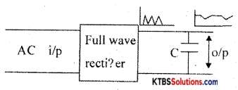
* Working
Question 25.
With a circuit diagram explain the working of the series positive clippers.
Answer:
Circuit diagram
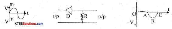
During the positive half cycle of the input, the diode is reverse biased so no current flows through – R. Hence out is zero (OA). During the negative half-cycle of the input, the diode is forward-biased. Hence there will be a negative half cycle that appears at the output (ABC).
Question 26.
Mention the steps involved in developing PCB. On the SMD resistor, it is printed as 222. What is its resistance?
Answer:
PCB Layout preparation, photoresist, PCB etching process,
PCB drilling, conductor plating, and PCB assembling.
222 = R = 22 × 102Ω = 2.2kΩ
PART-D
Answer any THREE questions. Each question carries FIVE marks. (3 × 5 = 15)
Question 27.
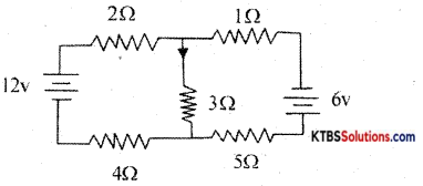
Calculate the current through 3Ω resistors Using superposition theorem.
Convert the following circuit into Thevenin’s equivalent circuit.
Answer:
Step 1: Short V2 = 6V find current through 3Ω say I1, It us I1 = 1A
Step 2: Short V1 = 12V find the current through 3Ω say I2. It is negative with respect to I1
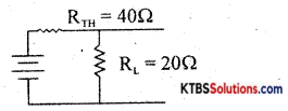
Find it is 40Ω. Find VTH, it is 16V.
VTH = 16V
Question 28.
An AC of 125V is applied to the primary of an ordinary transformer of power efficiency η = 60% so that the secondary current is 500mA. If the loss of power in the core and coil of it is low, calculate primary current, secondary voltage, output power, and input power.
Answer:
P1 = P0 + PL; η = \(\frac{\mathrm{p}_{0}}{\mathrm{p}_{\mathrm{i}}}=\frac{\mathrm{P}_{0}}{\mathrm{P}_{\mathrm{o}}+\mathrm{P}_{\mathrm{L}}}\)
P0 = \(\frac{\mathrm{P}_{\mathrm{L}}}{\frac{1}{\eta}-1}\) 15W;
P0 = IsVs → Vs = 30V
Pi = P0 + PL = 25W
![]()
Question 29.
The following components are used in the LRC series circuit. R = 100Ω, L = 1 mH and C = 1000μF. An AC, v = 200 sin 100 t is applied to it. Calculate impedance, power factor, and resonant frequency of the LRC circuit.
Answer:
v = 200 sin 100π t = V sin 27πt – f = 50 Hz
XL = 2πfL → XL = 0.3142Ω;
Xc = l/(2πfC) → Xc = 3.142π;
Z = \(\sqrt{R^{2}+\left(X_{L}-X_{c}\right)^{2}}\) = 100.041Ω
Power factor = cosΦ = R/Z = 0 99959; f = \(\frac{1}{2 \pi \sqrt{L C}}\) = 159.1Hz
Rs = 40.0
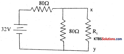
Question 30.
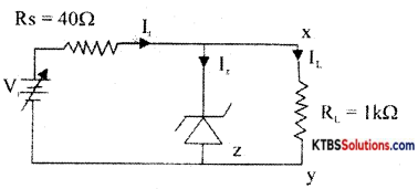
Where Z-zener diode of Vz = 10V, Pz = 2W; Izmin . for voltage regulation is 5mA. Calculate Imax, IL, vi min, and vi max. for voltage regulation, suppose in the above circuit if Vi = 20V, what should be the minimum load resistance (RL) required for voltage
Answer:
Iz max = \(\frac{P_{z}}{V_{z}}=\frac{2}{10}\) = 200mA;
It = Iz min + IL = 15 m A;
It max = Iz max + IL = 210 mA,
IL = \(\frac{\mathrm{V}_{\mathrm{o}}}{\mathrm{R}_{\mathrm{L}}}=\frac{\mathrm{V}_{\mathrm{z}}}{\mathrm{R}_{\mathrm{Z}}} \frac{10}{10^{3}}\) = 10mA
Vi min = It min min Rs + Vz = 16V
Vi max = It max Rs + Vz = 84V
For Vi = 20V, IL = \(\frac{V_{i}-V_{z}}{R s}\) = 25mA,
Ii max= It – Iz min = 20mA, RL min = \(\frac{\mathrm{V}_{\mathrm{z}}}{\mathrm{I}_{\mathrm{Lmax}}}\) = 500Ω
Question 31.
Convert (A1F)16 into equivalent binary number subtract (101)2 from (1010)2 using 2’s complement method.
Answer:
(A1F) = (10100001111)2
2’s complement subtraction.

2‘s Compliment of subtrahend(0110)2 (1010)2
2 ‘s Compliment of subtrahend + minuend = (10100)2
Extra carry: So the answer is positive. Write the rest of the bits ignoring carry with a positive sign that gives the answer. Ans = + (0100)2
(b) Answer any four questions. Each question carries five marks. (4 × 5 = 20)
Question 32.
(a) With a circuit diagram derive an expression for effective resistance of the parallel combination of resistors.
(b) When do we prefer this combination? (4 + 1)
Answer:
- Circuit diagram.
- Derivation of R.
- To get lesser resistance from the standard resistors parallel combination is preferred
Question 33.
(a) What are active and apparent powers? Give the relation between them.
(b) Explain the charging and discharging of a capacitor in the RC circuit when DC is applied. (2 + 3)
Answer:
Average power dissipated in an AC circuit is called active power or real power.
- The power a circuit seems to be drawing from an AC source is called apparent power
- Circuit dia m.
- Explanation:
- Charging,
- Discharging.
![]()
Question 34.
(a) Derive an expression for the effective capacitance of parallel combination of capacitors.
(b) What happens to capacitance when a dielectric medium is introduced between plates of a capacitor? (3 + 2)
Answer:
Circuit diagram.
- Derivation of C
- Capacitance increases
Question 35.
(a) What is an active component?
(b) With a diagram explain the working of dynamic (moving coil) loudspeaker. (1 + 4)
Answer:
It is an electronic component that supplies energy to the circuit. OR these are the components that can rectify or amplify or change one form of energy into another form
- Diagram.
- Working.
Question 36.
What is a rectifier? Draw the circuit diagram of the full-wave rectifier, explain its working. Draw the input and output waveforms.
Answer:
It is an electronic circuit that converts ac into dc.
- Circuit diagram.
- Working.
- Input and output waveforms.
Question 37.
(a) Show that A + A̅B = A + B using Boolean laws. Draw the circuit diagram and output waveform
(b) Draw the circuit diagram and output waveform of the monostable multivibrator using IC 555. What is the significance of the duty cycle? (2 + 3)
Answer:
LHS = A+ A̅B = A.1 + A̅B = A(1 + B) + A̅B
= A + AB + A̅B = A + B(A + A̅) = A + B.1
= A + B = RHS
- Circuit diagram
- Wave form.
- The duty cycle signifies that how long the multivibrator is in ON condition.