Students can Download 1st PUC Electronics Previous Year Question Paper March 2017 (South), Karnataka 1st PUC Electronics Model Question Papers with Answers helps you to revise the complete syllabus.
Karnataka 1st PUC Electronics Previous Year Question Paper March 2017 (South)
Time: 3.15 Hours
Max Marks: 70
Instructions:
- The question paper contains four parts.
- Part-A has no choice.
- Part – D contains two subparts: (i) Problems (ii) Essay type questions.
- Draw the circuit diagrams wherever necessary.
PART-A
Answer all of the following questions (10 × 1 = 10)
Question 1.
Name the most commonly used semiconductor material in device fabrication.
Answer:
Silicon
Question 2.
State Ohm’s law.
Answer:
I ∝ V
Question 3.
Write an expression for the instantaneous value of AC voltage.
Answer:
v = Vm sin wm t
Question 4.
What is the value of the SMD resistor with code 223?
Answer:
R = 223 = 22 × 103 = 22kΩ
![]()
Question 5.
Does a transformer work with DC input?
Answer:
No
Question 6.
Name the majority charge carriers in P-type semiconductors.
Answer:
Holes
Question 7.
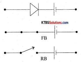
Draw the symbol of the photodiode.
Answer:

Question 8.
Mention the heavily doped region of a transistor.
Answer:
Emitter
Question 9.
Define 1’s complement of a binary number.
Answer:
1’s complement of a binary number is obtained by changing 1 to 0 and 0 to 1.
Question 10.
Mention any one type of seven-segment display.
Answer:
The common anode or common cathode.
PART-B
Answer any five of the following questions (5 × 2 = 10)
Question 11.
Write any two applications of the cathode-ray oscilloscope.
Answer:
- It is used to measure AC/DC voltage.
- It is used to measure the time period and frequency of AC.
Question 12.
Discuss the merits of a multimeter.
Answer:
- Small in size and easily portable.
- Several measuring functions can be performed.
Question 13.
Mention the factor on which the capacitance of a capacitor depends.
Answer:
- Area of plates
- Distance between plates
- The dielectric constant of the material between the plates.
![]()
Question 14.
Distinguish between microphone and speaker.
Answer:
- Microphone converts sound energy into an electrical audio signal.
- The loudspeaker converts an electrical signal into sound waves of varying pressure.
Question 15.
Define inductive reactance. Give the expression for inductive reactance.
Answer:
Inductive reactance is the opposition offered by an inductor for the flow of AC through it
XL = 2πfL.
Question 16.
Explain the second approximation of a semiconductor diode.
Answer:
According to the second approximation, the diode will not conduct until the forward bias voltage exceeds the knee voltage VK (the diode is a practical diode).
Question 17.
Calculate the emitter current IE in a transistor for β = 100 and IB = 10mA.
Answer:
β = \(\frac{\mathrm{I}_{\mathrm{C}}}{\mathrm{I}_{\mathrm{B}}}\)
Ic = βIB = 100 × 10 × 10-6 = 1 mA
IE = IB + Ic = 001 + 1 = 1.01 mA
Question 18.
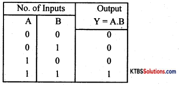
Write the truth table of two Input AND – gate.
Answer:
PART-C
Answer any five of the following questions (5 X 3 = 15)
Question 19.
Write a note on defence applications of electronics.
Answer:
In defence, Radar, Sonar and infrared systems are used to detect and locate warships, jet fighters and submarines. Missiles controlled by electronic signals can target enemies very accurately over long distances. Electronic security systems are used across the border to guard the country.
Question 20.
Explain the voltage divider rule.
Answer:
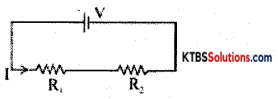
V1 = IR1 = \(\frac{V R_{1}}{R_{1}+R_{2}}\)
V2 = IR2 = \(\frac{V R_{2}}{R_{1}+R_{2}}\)
Question 21.
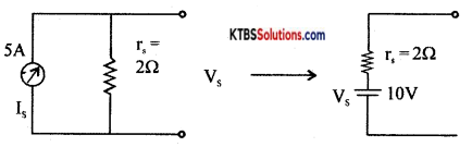
Convert the current source of SA with internal resistance 2C into a voltage source.
Answer:
VS = ISRS = 5 × 2 = 10V.
Question 22.
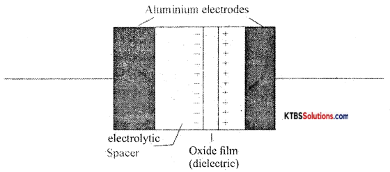
Write the constructional features of the electrolytic capacitor.
Answer:
The electrolytic capacitor has two sheets of aluminium foils separated by a layer of absorbent paper or plastic gauge. The gauge is soaked in a paste of electrolyte of borax or phosphate. They are rolled up and placed ¡n a cylindrical aluminium container. The inner foil acts as the positive plate and the negative terminal is attached to an aluminium container that contacts the outer foil. After assembling, a DC voltage is applied to the capacitor terminals oxide on the surface of the positive plate next to the electrolyte.
The oxide layer acts as the dielectric. As the oxide layer formed is extremely thin which acts as a dielectric material, these capacitors have a large capacitance value. An electrolytic capacitor is polarity sensitive. 1f connected wrongly, gas forms within the electrolyte and the capacitor may be damaged due to gas formed may lead to an explosion. Hence electrolytic capacitors are polarity sensitive.
Their capacitance value ranges from 1 µF to 0.01 µF with a voltage, rating of 50V to 10KV. Electrolytic capacitors are suitable for high-frequency applications and in radio frequency and microwave systems.
![]()
Question 23.
Compare LED display with LCD display.
Answer:
| LED Display | LCD Display |
| 1. It emits light | I. It reflects light. |
| 2. It has more brightness | 2. It has less brightness |
| 3. Operates from | 3. Operates from 3 to 20 VDC. |
Question 24.
Draw the output characteristics of a transistor in CE configuration. Show the different regions of operation.
Answer:
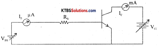
The circuit to plot the CE characteristics of the transistor is as shown in the diagram.
The two types of characteristics are:
- Input characteristics.
- Output characteristics.
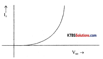
Input Characteristics:
It gives the relationship between input voltage VBE and the input current Is when the output voltage VCE is kept constant. VBE is varied and corresponding ‘B values are noted keeping VCE constant. The input characteristics curve is similar to that of a forward-biased semiconductor diode as emitter-base junction a pn junction.
Input resistance Rm = \(\frac{\Delta \mathrm{V}_{\mathrm{BE}}}{\Delta \mathrm{I}_{\mathrm{B}}}\)
CE output characteristics
It is a graph of output collector current Ic against output collector to emitter voltage VCE for a constant input base current IB.
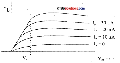
From the graph, it is clear that the output current Ic depends upon input current IB and VCE has no control over Ic.
Output resistance, Rout = \(\frac{\Delta \mathrm{V}_{\mathrm{CE}}}{\Delta \mathrm{I}_{\mathrm{C}}}\)
Question 25.
Convert: (i) (ADD)16 to decimal (ii) (194)16 to binary.
Answer:
(i) (ADD)16 = A × 162 + D × 16′ + D × 16°= 10 × 256 + 13 × 16 + 13 × 1 =(2781)10
(ii) (194)16 = (000110010100)2
Question 26.
What are the advantages of the printed circuit boards?
Answer:
- the circuit looks neat without hanging wires.
- Much higher density components are placed in PCB.
- Very precise control over the circuit components.
PART-D
Answer any three questions: (3 × 5 = 15)
Question 27.
Using Thevenin’s theorem find the current through 10Ω resistance in the following circuit.
Answer:
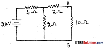
VTH= V across 2Ω = I × 2 = \(\frac{24}{4+2}\) = 8V
RTH =2 + (4 ∥ 2) = 2 + \(\frac{4 \times 2}{4+2}\) = 2 + \(\frac{8}{6}\) = 3.33Ω
Current through 10Ω resistance,
load current IL = \(\frac{V_{\text {Th }}}{R_{T h}+R_{L}}=\frac{8}{3.33+10}\) = 0.6A.
Question 28.
A transformer has 500 turns in the primary and 250 turns in the secondary. What is the turn’s ratio? How much is the secondary voltage with a primary voltage of 220V?
Answer:
Np = 500, Ns = 250;
Turns Ratio = Ns: Np = 250: 500 = 1: 2
\(\frac{\mathrm{N}_{\mathrm{s}}}{\mathrm{N}_{\mathrm{P}}}=\frac{\mathrm{V}_{\mathrm{s}}}{\mathrm{V}_{\mathrm{P}}}, \frac{250}{500}=\frac{\mathrm{V}_{\mathrm{s}}}{220}\), Vs = 110 V
![]()
Question 29.
An inductor of 20mH is connected in series with a resistor of 50Ω. The combination is connected to 220V/50Hz source. Calculate.
(i) Impedance of the circuit
Answer:
Z = \(\sqrt{R^{2}+X_{L}^{2}}=\sqrt{R^{2}+(2 \pi f L)^{2}}=\sqrt{(50)^{2}+\left[2(3.14) 50 \times 20 \times 10^{-3}\right]^{2}}\) = 50.39Ω
(ii) Current in the circuit
Answer:
I = \(\frac{\mathrm{V}}{\mathrm{Z}}=\frac{220}{50.39}\) = 4.36A
(iii) Phase angle.
Answer:
Φ = tan-1\(\left(\frac{\mathrm{X}_{\mathrm{L}}}{\mathrm{R}}\right)\) = tan-1\(\left(\frac{6.28}{50}\right)\) = tan-1(0.1256) = 7°12′
Question 30.
For a Zener diode voltage regulator, find (i) load voltage (ii) voltages across the series resistance Rs. (iii) The current through the Zener diode.
Answer:
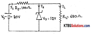
(i)VL = Vz = 12V
(ii) Voltage across Rs is
VRS = Vs – Vz = 20 – 12 = 8V
(iii) Is = IRS = \(\frac{\mathrm{V}_{\mathrm{RS}}}{\mathrm{R}_{\mathrm{S}}}=\frac{8}{100}\) = 0.08A
IL = \(\frac{\mathrm{V}_{L}}{\mathrm{R}_{\mathrm{L}}}=\frac{12}{680}\) = 0.01A;
Iz = Is – IL = 0.08 – 0.01 = 0.07A or 70mA
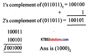
Question 31.
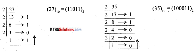
Subtract (27) from (35) using 2’s complement method.
Answer:
Answer any four of the following questions (4 × 5 = 20)
Question 32.
Derive an expression for the equivalent resistance of two resistors connected in parallel. (3 + 2)
Answer:
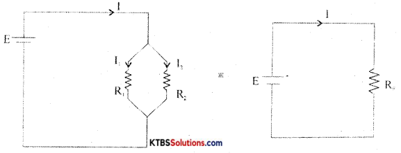
Consider two resistors R1 and R2 connected ¡n parallel between the same two common points.
In parallel combination, the voltage across each resistor is the same.
Let I1 and I2 be the currents through the resistors R1 and R2.
The current from the cell equals the sum of the currents through the two resistors, i.e.,
I = I1 + I2 = \(\frac{\mathrm{V}}{\mathrm{R}_{1}}+\frac{\mathrm{V}}{\mathrm{R}_{2}}\) = V\(\left(\frac{1}{R_{1}}+\frac{1}{R_{2}}\right)\) →(1)
Equivalent or effective resistor Rp is a single resistor that has the same effect as a tile parallel combination. If Rp is the effective resistor, then I = \(\frac{\mathrm{V}}{\mathrm{Rp}}\) →(2)
From equations (1) and (2)
\(\frac{\mathrm{V}}{\mathrm{Rp}}\) = V\(\left(\frac{1}{R_{1}}+\frac{1}{R_{2}}\right)\)
\(\frac{1}{\mathrm{Rp}}=\frac{1}{\mathrm{R}_{1}}+\frac{1}{\mathrm{R}_{2}}\)
Hence, the reciprocal of effective resistance of a number of resistors in parallel is the sum of the reciprocals of the individual resistances.
![]()
Question 33.
(a) Explain the construction and working of a thermistor.
(b) Write any two applications of LDR. (3 + 2)
Answer:
- LDR is used in switches and alarms.
- It is used in counters.
Question 34.
Discuss the growth and decay of current in RL- Circuit.
Answer:
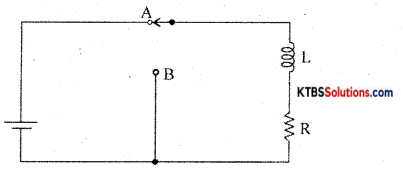
Consider an inductor Land a resistor R connected in series to a cell. When the switch is in position A, the current in the circuit grows exponentially.
The current I at a time after the switch is placed ¡n the position A is I = I0e-(R/L)t, where Io is the maximum current.
The time constant of RL circuits is the time taken by the current to grow to 63.2% of the maximum value.
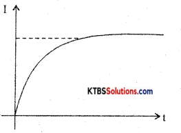
Growth of current in RL circuit
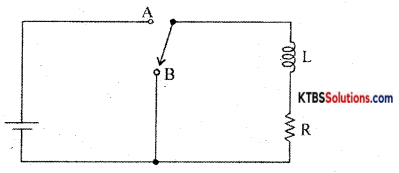
When the switch is in position A, the current in the circuit increases exponentially and reaches a maximum value. When the switch is in position R, the current in the circuit starts decaying exponentially with time.
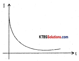
Decay of current
The value of current at timer after the switch is placed in position B is I = I0e(-R/L)t where I0 is the maximum current.
The time constant of the RL circuit is the time taken by the RL circuit for the current to decay to 36.8% of its maximum value.
Question 35.
Explain the construction and working of a centre-tapped full-wave rectifier. Show its input and output waveforms.
Answer:
A full-wave rectifier is a circuit that converts the entire AC input cycle into varying DC output.
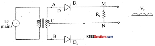
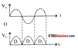
During the positive half cycle of AC input, A is positive and B is negative. The diode D1 is forward biased and conducts. The diode D2 is reverse biased and does not conduct. The current flows along AD1MNC.
During the negative half cycle of AC input. A is negative and B ¡s positive. The diode D1 is reverse biased and does not conduct. Hence, the current flows along BD2MNC.
Thus the load current flows in the same direction M toN during both the half cycles of AC input. The peak inverse voltage (PIV) of this rectifier is 2Vm where Vm is the peak or maximum value of the secondary voltage.
RMS value of voltage, Vrms = \(\frac{\mathrm{V}_{\mathrm{m}}}{\sqrt{2}}\)
Ripple factor (r) is the ratio of the RMS value of the AC component of load voltage to the average value of load voltage.
r = \(\frac{\mathrm{V}_{\mathrm{rms}}}{\mathrm{V}_{\mathrm{avg}}}\) = 0.48
Efficiency is the ratio of DC output power to AC input power.
η = \(\frac{\text { DC power to load }}{\text { AC input power }}\) = 0.812 or 81.2%
![]()
Question 36.
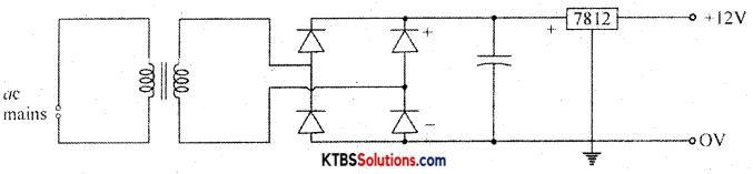
(a) Draw the circuit diagram of a fixed positive regulated power supply using IC-7812.
Answer:
(b) Determine the current through kW resistor in the following circuit.
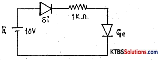
Answer:
I = \(\frac{10-(0.7+0.3)}{1 \mathrm{k} \Omega}=\frac{9}{1 \times 10^{3}}\), I = 9mA
Question 37.
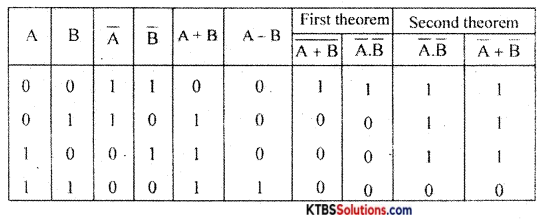
(a) State De-Morgans’ theorems.
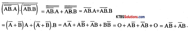
y = \(\overline{(\overline{\overline{\mathrm{AB}} \cdot \mathrm{A}}) \cdot(\overline{\overline{\mathrm{AB}} \cdot \mathrm{B}})}\)
Answer:
First theorem: The complement of a logical sum is equal to the logical product of complements
\(\overline{\mathrm{A}+\mathrm{B}}\) =A.B
Second theorem: The complement of a logical product is equal to the logical sum of complements.
\(\overline{\mathrm{AB}}\) = A+B
Proof:
(b) Simplify the Boolean equations.
Answer: