Students can Download 1st PUC Electronics Previous Year Question Paper March 2019 (South), Karnataka 1st PUC Electronics Model Question Papers with Answers helps you to revise the complete syllabus.
Karnataka 1st PUC Electronics Previous Year Question Paper March 2019 (South)
Time: 3.15 Hours
Max Marks: 70
Instructions:
- The question paper contains four parts.
- Part – A is Compulsory
- Part – D has Two Parts: (I) Part I is Problems (ii) Part II is of essay type questions
- Circuit diagram / tining diagram/truth tables are drawn wherever necessary.
- Problems without necessary Formula / Formulae carry no mark.
PART-A
I. Answer ALL questions. (10 × 1 = 10)
Question 1.
Name the most commonly used semiconductor material in device fabrication.
Answer:
Silicon.
Question 2.
Give an example for DC Source.
Answer:
Cells.
Question 3.
What is a pulse oximeter?
Answer:
It is a device used to detect the saturation level of hemoglobin in the blood.
Question 4.
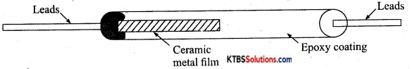
Draw the cross-sectional view of the metal film resistor.
Answer:
Question 5.
The time constant of an RL circuit is 4ms. If L = 100 mH calculate the value of resistance.
Answer:
R = \(\frac{L}{T}=\frac{100 \times 10^{-3}}{4 \times 10^{-3}}\) = 25Ω
![]()
Question 6.
Write an expression for space charge capacitance in the case of the reverse-biased diode.
Answer:
Cr = \(\frac{\in \mathrm{A}}{\mathrm{W}}\)
Question 7.
What is a rectifier?
Answer:
A circuit that converts ac to varying dc.
Question 8.
Write one important application of a transistor.
Answer:
Amplifier or switch.
Question 9.
What is the purpose of l’s complement of a binary number system?
Answer:
1 ‘s complement helps to do subtraction with the help of addition.
Question 10.
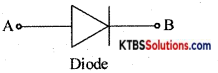
Part number of a diode is 1N4007, draw it a symbol.
Answer:
PART-B
Answer any FIVE questions. (5 × 2 = 10)
Question 11.
Mention any two properties of charges.
Answer:
Frequency of ac is the number of AC cycles completed in one second.
f = \(\frac{1}{\mathrm{~T}}=\frac{1}{10 \times 10^{-3}}=\frac{1000}{10}\) = 100Hz
Question 12.
Write the importance of ultrasound scans.
Answer:
Ultrasound scan
- Helps to monitor the growth of the unborn child and check abnormalities.
- detect abnormal widening of blood vessels.
- detect abnormalities of heart valves.
Question 13.
Briefly explain the role of a dielectric in a capacitor.
Answer:
Dielectric medium decreases potential and increases the capacitance of the capacitor.
![]()
Question 14.
Define inductive reactance and give the expression for the capacitive reactance.
Answer:
Inductive reactance is the opposition offered by an inductor to the flow of ac.
Question 15.
Explain the phenomenon of diode reverse breakdown.
Answer:
When a heavily doped diode that has a narrow depletion region is subjected to a reverse voltage, the high electric field at the junction breaks covalent bonds. Hence a large number of electron holes are produced and the diode is said to be under Zener breakdown.
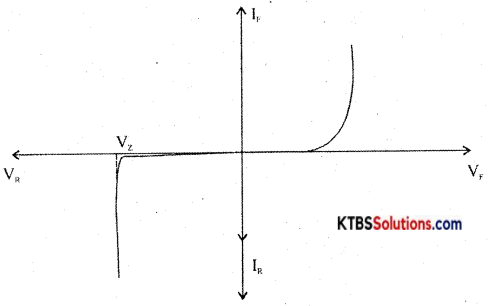
V – l characteristics of Zener diode
Question 16.
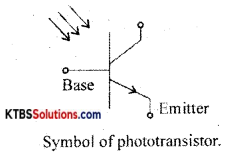
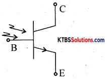
What is a phototransistor? Draw its Symbol.
Answer:
A phototransistor is a three-terminal optoelectronics device.
Question 17.
Find the value of β if α = 0.99.
Answer:
β = \(\frac{\alpha}{1-\alpha}=\frac{0.99}{1-0.99}\) = 99
![]()
Question 18.
Write the symbol of the I R transistor and PNP transistor.
Answer:
PART-C
Answer any FIVE questions. (5 × 3 = 15)
Question 19.
Mention three applications of the internet.
Answer:
E – learning E -mailing E – banking
Question 20.
Explain the construction and working of a Thermistor.
Answer:
Thermistors are used in
- temperature measurement
- temperature control in air conditioners.
- alarm systems
- liquid level detection.
Question 21.
Mention different types of transformers.
Answer:
- Power transformer.
- Audio frequency transformer.
- Radiofrequency transformer.
![]()
Question 22.
Discuss the charging of capacitor in RC circuit when DC source is connected.
Answer:
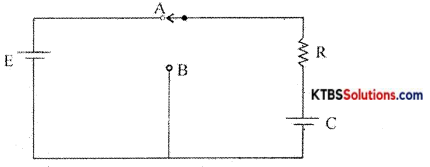
Consider a resistor R and a capacitor C connected in series with a battery of emf E. When the switch is in position A, the capacitor C gets charged through R exponentially with time.
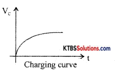
Hence Voltage across the capacitor increases exponentially and the current in the circuit decreases exponentially. When the capacitor is fully charged, the current becomes Zero. The instantaneous value of voltage across the capacitor during charging is given by
V = V0(1 – e1/RC)
The instantaneous value of current is I =I0e1/RC Time constant (τ) of an RC circuit is the time taken by the capacitor to charge to 63.2% of maximum current.
Question 23.
Derive an expression for Fr of a series resonant circuit.
Answer:
Consider an AC circuit consisting of inductance (L), capacitor C and a resistance R connected in series to an AC source. Let the instantaneous voltage of the ac source be
v = Vm sin wt
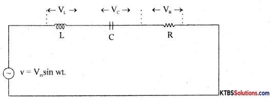
Let VL, VR, Vc be the voltages across the inductor, Resistor, and capacitor.
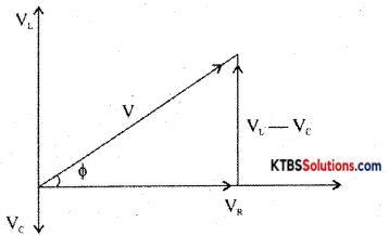
Result Voltage V = \(\sqrt{V_{\mathrm{R}^{2}}+\left(\mathrm{V}_{\mathrm{L}}-\mathrm{V}_{\mathrm{C}}\right)^{2}}\)
= \(\sqrt{I^{2} R^{2}+\left(I X_{L}-I X_{C}\right)^{2}}\)
= \(\sqrt{I^{2}\left[R^{2}+\left(X_{L}-X_{C}\right)^{2}\right]}\) = I\(\sqrt{R^{2}+\left(X_{L}-X_{C}\right)^{2}}\)
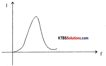
As the frequency of AC source is increased, the capacitive reactance of the capacitor decreases and .inductive reactance of the .inductnr .increases . The values of XL and Xc will be same at resonance frequency r’
XL = Xc
2πfR2l = \(\frac{1}{2 \pi \mathrm{f}_{\mathrm{r}} \mathrm{C}}\)
4π2fr2LC = 1
fr2 = \(\frac{1}{4 \pi^{2} \mathrm{LC}}\) , fr = \(\frac{1}{2 \pi \sqrt{\mathrm{LC}}}\)
The current in RLC circuit will be maximum at resonance the variation of current with frequency is as shown below:
![]()
Question 24.
A service resonant circuit has R = 100Q, C = 0.1 μF produces a resonant frequency of 3KHz. Find the value of L?
Answer:
f = \(\frac{1}{2 \pi \sqrt{\mathrm{LC}}}\) ⇒ f2 = \(\frac{1}{4 \pi^{2} L C}\) ⇒ L = \(\frac{1}{4 \pi^{2} \mathrm{Cf}^{2}}\) = 28.17mH
Question 25.
Write a note on Barrier potential with respect to the PN-junction diode.
Answer:
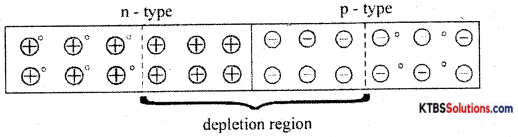
A pn junction is formed when one side of a pure semiconductor crystal is doped with a trivalent impurity and the other side with a pentavalent impurity.
The n-type material has electrons as majority charge carriers and holes as minority charge carriers. The p-type material has holes as majority charge carriers and electrons as minority charge carriers. Due to this, there is a concentration gradient across the junction and electrons move from n-type to p-type whereas holes move from p-type to n-type region.
The transfer of electrons and holes across the junction is known as diffusion. The recombination of electrons and holes makes the region near injunction depleted of electrons and holes.
The depletion region is the region near pn junction which is depleted of mobile charge carriers namely electrons and holes.
The small potential difference developed across the pn junction due to immobile positive and negative ions is called barrier potential. The barrier voltage is 0.3V for Germanium and 0.7V for silicon. The barrier potential stops the diffusion of charge carriers across the pn junction.
Question 26.
List any three advantages of the datasheet.
Answer:
- For technical communication.
- To help people to choose products.
- To help people to use the products.
PART-D
Answer any THREE questions: (3 × 5 = 15)
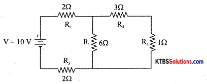
Question 27.
Using Thevenin’s theorem, find the current through the If 2 resistor, for the circuit shown below.
Answer:
VTh = \(\frac{\mathrm{VR}_{3}}{\mathrm{R}_{1}+\mathrm{R}_{2}+\mathrm{R}_{3}}\) = 6V
RTh = (R1 + R3) ∥ R2 + R4 = 5.4Ω
IL = \(\frac{\mathrm{V}_{\mathrm{Th}}}{\mathrm{R}_{\mathrm{Th}}+\mathrm{R}_{\mathrm{L}}}\) = 0.93A
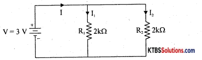
Question 28.
Find the current flowing through the circuit, also find the branch currents.
Answer:
RT = R1 in parallel with R2
= \(\frac{\mathrm{R}_{1} \mathrm{R}_{2}}{\mathrm{R}_{1}+\mathrm{R}_{2}}=\frac{2 \times 2}{2+2}\) = 1 kΩ
I = \(\frac{\mathrm{V}}{\mathrm{R}_{\mathrm{T}}}=\frac{3}{1 \times 10^{3}}\) = 3mA ⇒ I1 = \(\frac{\mathrm{IR}_{\mathrm{T}}}{\mathrm{R}_{1}}\) = 1.5mA ⇒ I2 = \(\frac{\mathrm{IR}_{\mathrm{T}}}{\mathrm{R}_{2}}\) = 1.5mA
Question 29.
A half wave rectifier uses a diode with a forward resistance of 50W. If the input ac voltage is 200 Vrms and the load resistance of 1 kW. Determine
(i) Im (ii) IDC (iii) Irms (iv) PIV and (v) δ
Answer:
Im = \(\frac{V_{m}}{R_{F}+R_{L}}=\frac{282}{50+1000}\) = 0.269 A
Idc = \(\frac{\mathrm{I}_{\mathrm{m}}}{\pi}\) = 0.085 A
Irms = \(\frac{\mathrm{I}_{\mathrm{m}}}{\sqrt{2}}=\frac{0.269}{1.414}\) = 0.134 A
PIV = Vm = 282 V
r = 1.21.
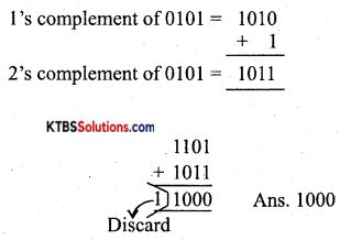
Question 30.
Subtract 1012 from 11012 using 2’s Complement method.
Answer:
![]()
Question 31.
Simplify Y = AB + A(\((\overline{B+C})\)).
Answer:
Y = AB + A\((\overline{B+C})\) 1
=AB + A(B̅.C̅)
=AB + A\(\overline{\mathrm{BC}}\)
= A(B + B̅C̅)
=A(B + C̅)
= AB + AC̅
II. Answer any FOUR questions. (4 × 5 = 20)
Question 32.
Write a note on AC generation.
Answer:
Consider an AC circuit consisting of inductance (L), capacitor C and a resistance R connected in series to an AC source. Let the instantaneous voltage of the ac source be
v = Vm sin wt
Let VL, VR, Vc be the voltages across the inductor, Resistor, and capacitor.
Result Voltage V = \(\sqrt{V_{\mathrm{R}^{2}}+\left(\mathrm{V}_{\mathrm{L}}-\mathrm{V}_{\mathrm{C}}\right)^{2}}\)
= \(\sqrt{I^{2} R^{2}+\left(I X_{L}-I X_{C}\right)^{2}}\)
= \(\sqrt{I^{2}\left[R^{2}+\left(X_{L}-X_{C}\right)^{2}\right]}\) = I\(\sqrt{R^{2}+\left(X_{L}-X_{C}\right)^{2}}\)
As the frequency of AC source is increased, the capacitive reactance of the capacitor decreases and .inductive reactance of the .inductnr .increases . The values of XL and Xc will be same at resonance frequency r’
XL = Xc
2π2fr2l = \(\frac{1}{2 \pi \mathrm{f}_{\mathrm{r}} \mathrm{C}}\)
4π2fr2LC = 1
fr2 = \(\frac{1}{4 \pi^{2} \mathrm{LC}}\) , fr = \(\frac{1}{2 \pi \sqrt{\mathrm{LC}}}\)
The current in RLC circuit will be maximum at resonance the variation of current with frequency is as shown below:
Question 33.
Explain the color-coding method of evaluating, the value of the resistor with one example.
Answer:
A mixture of finely divided carbon and powdered insulating material forms the resistor element. The mixture is molded into a cylindrical shape. The proportion of the mixture is adjusted to get the desired value of resistance. Metal caps with leads of tinned copper wire are joined lo two ends of carbon-coated resistor for external connection.
As the leads are joined axially from the ends, they are called axial leads. The non-conductive material is coated on the resistor element for insulation and mechanical strength. To specify the resistance of the resistor, a band of colors is marked on the body of the resistor.
Carbon composition resistors are smaller in size and cheap. They are available in the resistance range of 1Ω to 2OMΩ Their power rating is \(\frac{1}{10}, \frac{1}{8}, \frac{1}{4}, \frac{1}{2}\)1 and 2W. These resistors are used where accuracy is not important.
![]()
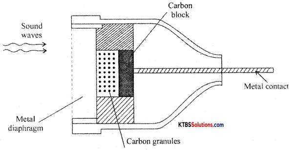
Question 34.
Distinguish between speaker and microphone.
Answer:
The microphone is a device that converts sound energy into an electrical signal. It has an insulating button loosely filled with carbon granules. The button is attached to a very thin steel diaphragm.
The diaphragm vibrates when sound waves strike it. Due to vibration, their is variation in the pressure on carbon granules, which changes the resistance of carbon granules in accordance with the pressure of sound waves.
Hence any change in the resistance of carbon granules produces a corresponding change in the current through the circuit. This varying current flowing through the primary coil produces an alternating voltage in the secondary of the transformer.
Question 35.
Explain the working of the sheet capacitor filter.
Answer:
Filters:
A filter is a circuit that removes the AC component from the rectifier output and allows pure DC to reach the load.
Series inductor filter:
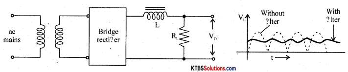
It has an inductor L in series with rectifiers output and loads RL.
The inductor opposes any change in current flowing through it. When the current through the inductor tries to change, a back emf is induced in the inductor which prevents the current from changing. Hence inductor offers a large opposition to the AC component and blocks AC and allows only DC to pass through. Thus DC voltage is developed across RL.
Shunt capacitor filter:
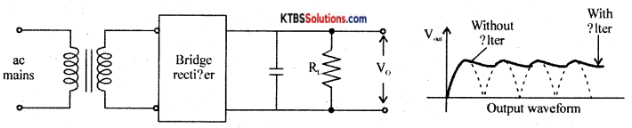
It has a large value capacitor connected in parallel with load R.
The capacitor blocks DC and allows AC to pass through. Hence it bypasses the AC component allowing DC to reach the load. Thus shunt capacitor filter removes most of the AC components.
When the output voltage of the rectifier is increasing, the capacitor charges to the peak value of the input. Beyond peak value, the rectifier diode becomes reverse biased and stops conducting.
Now capacitor discharges through RL. The capacitor discharge until the output of the rectifier again increases to a value greater than capacitor voltage. Now diode becomes forward biased and conducts.
Thus the almost constant output is obtained across RL.
LC filter or L type filter:
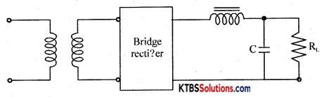
This filter combines the current smoothing action of a series inductor with the voltage stabilizing action of the shunt capacitor filter. The inductor allows DC current to pass through easily offering high reactance to AC.
Any variations or ripple that remains after passing through the inductor is bypassed to the ground by the capacitor. Hence DC voltage reaches the load.
Question 36.
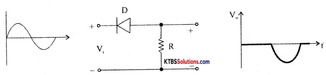
Explain positive diode clippers with input and output waveforms.
Answer:
Question 37.
With neat circuit diagram describe the working of the DTL NOR gate.
Answer:
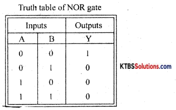
NOR gate is a logic circuit whose output is HIGH only when both its inputs are LOW
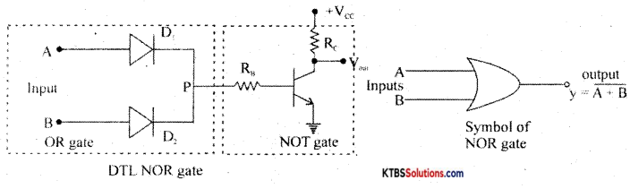
Diodes D1 and D2 form OR gates and the transistor act as NOT gates.
Case (I) When A = 0, B = 0, the diodes are not forward biased and they do not conduct.
Hence voltage P is zero. This zero voltage makes the transistor go to cut-off condition and therefore output is HIGH.
Case (ii) When A = 0, B = 1, D1 does not conduct but D2 conducts. Hence voltage at P is +Vcc and it drives the transistor to saturation and output becomes LOW.
Case (iii) When A = 1, B = 0, D1, conducts and D2 does not conduct. Hence voltage at P is +Vcc and this makes the transistor Q go to saturation. Hence output becomes LOW.
Case (iv) When A = 1, B = 1, both diodes conduct as they are forward biased. Then voltage at P is +Vcc and the transistor is driven to saturation. The output at the collector becomes LOW.