Students can Download 1st PUC Electronics Previous Year Question Paper March 2020 (South), Karnataka 1st PUC Electronics Model Question Papers with Answers helps you to revise the complete syllabus.
Karnataka 1st PUC Electronics Previous Year Question Paper March 2020 (South)
Time: 3.15 Hours
Max Marks: 70
Instructions:
- The question paper contains four parts A, B, C, and D.
- Part – A has no choice
- Part – D has Two Parts: (i) Part I is Problems (ii) Part II is of essay type questions
- Circuit diagram / tining diagram/truth tables are drawn wherever necessary.
- Problems without necessary Formulae carry no mark.
PART-A
I. Answer ALL questions. (10 × 1 = 10)
Question 1.
Mention the S.I. Unit of electric charge.
Answer:
Coulomb.
Question 2.
Define Ohm’s law.
Answer:
The current flowing through a conductor is directly proportional to the potential difference across the ends of the conductor when the temperature and other physical conditions of the conductor are kept constant.
Question 3.
Write an expression for energy stored in a capacitor.
Answer:
E = \(\frac{1}{2}\)CV2.
Question 4.
Define the time constant of the RC – circuit.
Answer:
The time constant of the RC circuit is the time taken by the capacitor to charge to 63.2% of the supply voltage.
![]()
Question 5.
Name any one donor impurity.
Ans.
Arsenic or Gallium.
Question 6.
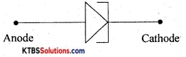
Draw the symbol of the tunnel diode.
Answer:
Question 7.
Mention the lightly doped region of a transistor.
Answer:
Base.
Question 8.
What is a phototransistor?
Answer:
The phototransistor is a three-terminal light-sensitive semiconducting device.
Question 9.
Write the decimal equivalent of (1110)2.
Answer:
(1110)2 = (14)10
Question 10.
How many nibbles are there in a byte?
Answer:
2 nibbles = 1 byte.
PART-B
Answer any FIVE questions. (5 x 2 = 10)
Question 11.
What is a glucometer? Expand ECG
Answer:
A glucometer is a device that measures the concentration of glucose in the blood.
ECG = Echo Cardio Gram.
Question 12.
Mention any two applications of the oscilloscope.
Answer:
- It is used to measure AC/DC voltage.
- It is used to measure the time period and frequency of ac.
![]()
Question 13.
Define inductive reactance. Give the expression for inductive reactance.
Answer:
Inductive reactance is the opposition offered by an inductor to the flow of ac.
XL = 2πfL
Question 14.
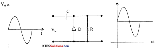
Draw the circuit diagram of a positive didode clampter with its input-output waveforms.
Answer:
Question 15.
Derive the relationship between α and β of a transistor.
Answer:
Question 16.
A transistor connected in CE-mode has β = 100, IB = 50 μA. Calculate Ic and α.
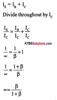
Answer:
β = \(\frac{\mathrm{I}_{\mathrm{C}}}{\mathrm{I}_{\mathrm{B}}}\)
Ic = β.IB = 100 × 50 × 10-4 = 5mA
α = \(\frac{\beta}{\beta+1}=\frac{100}{101}\) = 0.990
![]()
Question 17.
Prove (A + A̅B) = A + B.
Answer:
A + A̅B = A.1 + A̅B (∵ A.1 = A)
= A(1 + B) + A̅B(∵ 1 = 1 + B)
= A + AB + A̅B
= A + B(A + A̅)
= A + B(1)(∵ A + A̅ = 1)
= A + B(∵ B.1 = B)
= RHS
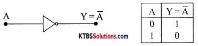
Question 18.
Draw the symbol and truth table of NOT-gate.
Answer:
PART-C
Answer any FIVE questions. (5 × 3 = 15)
Question 19.
What is the internet? Mention a few applications of the internet.
Answer:
Internet is the largest and the most effective communication platform.
The Internet provides several applications like World Wide Web, E-mail, e-commerce. Chat, Teleconference and Telemedicine.
Question 20.
Derive an expression for equivalent resistance of two resistors connected in series.
Answer:|
Consider two resistors R1 and R2 connected in series to a cell of emf E. In a series combination, the resistors are connected end to end and the same current flows through each of them.
The emf of the cell equals voltage drops across each of the resistors
E = V1 + V2 = IR1 + IR2 {frorn ohms law}
E = I(R1 + R2)→(1)
The effective or equivalent resistor is a single resistor that has the same effect as a combination of resistors. If R. is the effective resistance, E = IR5 → (2)
From the equations (1) and (2), IR = I(R1 + R2)
∴ Rs = R1 + R2
∴ The effective resistance of resistors in series in the sum of the individual resistances.
![]()
Question 21.
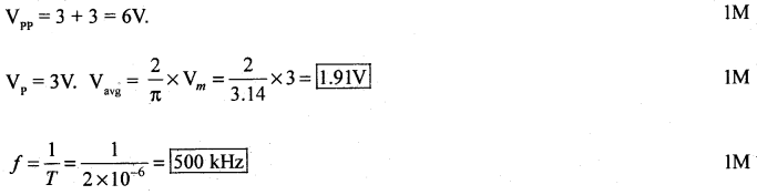
Calculate Vpp.Value and frequency of an AC waveform given below.
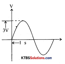
Answer:
Question 22.
Explain the factors on which the self-inductance of a coil depends.
Answer:
Self-inductance depends on the number of turns, length, and area of the cross-section of the coil.
Question 23.
Classify solids based on the energy band diagram.
Answer:
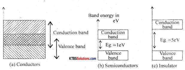
Conductors: These are materials that allow the current to flow through them easily. In conductors, the valence band and conduction band overlap completely due to which the valence electrons drift to the conduction band easily. Even at room temperature, there is a large number of free electrons. Hence due to the small voltage applied a large current flows through them.
Semiconductors: These are the materials with electrical conductivity lying between those of conductors and insulators. The forbidden energy gap between the valence band and conduction band is 0.7 eV for germanium and 1. 1 eV for silicon. At absolute zero, a semiconductor acts as an insulator. As the temperature increases, more valence electrons jump to the conduction band. Hence the conductivity of semiconductors increases with an increase in their temperature.
Insulators: insulators are materials that do not allow the electric current to flow through them easily. The valence band is completely filled and the conduction band is completely empty in insulators. The forbidden energy band between the conduction band and valence band is nearly 5eV. In the conduction band, there are no free electrons present at room temperature. Hence, the insulators do not conduct at all at room temperature.
Question 24.
Draw the circuit diagram of HWR and explain its working.
Answer:
Half wave rectifier is a circuit that removes one-half cycle of the AC input and produces a pulsating DC output voltage.
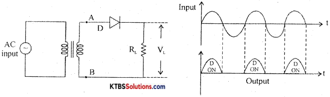
It has diode D in series with a load resistor RL. The AC mains voltage to be rectified is applied to the primary of a transformer and voltage induced across secondary is applied to the rectifier.
During the positive half cycle, A ¡s positive and B is negative. The diode is forward biased and conducts and the diode acts as a closed switch. Hence, the positive half cycle of the voltage is developed across the load resistor RL.
During the negative half-cycle, A is negative and B is positive. The diode is reverse biased and does not conduct as it acts as an open switch. Hence there is no output. The output waveform across RL has only positive half cycles. Ripple factor is the ratio of the RMS value of(r) the AC component of the load voltage to the average value of load voltage.
r = \(\frac{\text { rms value of AC component }}{\text { value of dc component }}\) = 1.21
Rectifier efficiency is the ratio of de output power to ac input power.
η = \(\frac{\text { DC output power }}{\text { AC input power }}\) = 0.406 or 40.6%
Question 25.
Give the comparison of Germanium (Ge) and silicon (Si) diodes.
Answer:
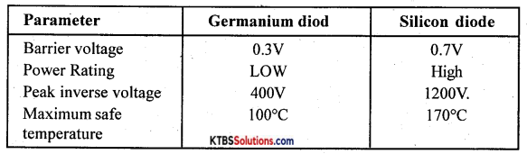
![]()
Question 26.
Write the steps involved in PCB designing.
Answer:
- Schemas
- PCB Etching
- Drilling
- Conductor Plating
- PCB Assembling
PART-D
Answer any three questions: (3 × 5 = 15)
Question 27.
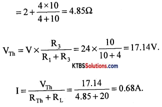
Using Thevenin’s theorem, find the current through 20Ω resistors in the following circuit.
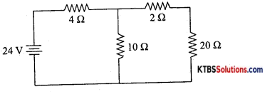
Answer:
RTh = 2 + 4Ω in parallel with 10Ω
Question 30.
For a zener diode voltage regulator with Vs = 20 V, Rs = 100Ω, RL = 680Ω and Vz = 12 V. Determine
(a) Load voltage
(b) Voltage drop across Rs
(c) Current through zener diode
Answer:
VL = Vz = 12 V
Vs = VB – Vz .
= 20 – 12
= 8V
Is = \(\frac{\mathrm{V}_{\mathrm{S}}}{\mathrm{R}_{\mathrm{S}}}=\frac{8}{100}\) = 0.08A.
IL = \(\frac{\mathrm{V}_{\mathrm{L}}}{\mathrm{R}_{\mathrm{L}}}=\frac{12}{680}\) = 0.017A.
lz = Is – IL = 0.08 – 0.017 = 10.063A
![]()
Question 31.
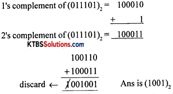
Subtract (29)10 from (38)10 using 2’s complement method.
Answer:
(29)10 = 011101
(38)10 = 100110
II. Answer any FOUR questions (4 × 5 = 20)
Question 32.
State and explain Kirchoff’s laws.
Answer:
- The sum of the currents flowing towards a ¡iode in a circuit is equal to the sum of the currents away from the node.
- The algebraic sum of EMFs in any closed loop of a network is equal to the algebraic sum of IR drops in that loop.
Question 33.
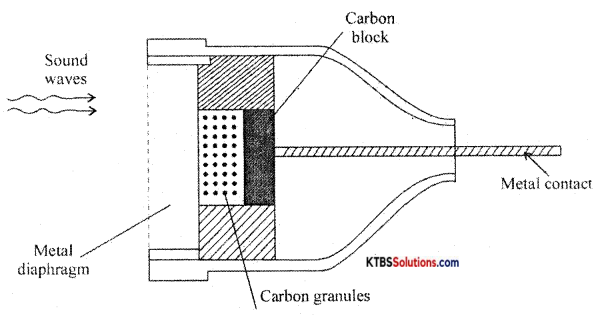
Explain the construction and working of the microphone.
Answer:
The microphone is a device that converts sound energy into an electrical signal. It has an insulating button loosely filLed with carbon granules. The button is attached to a very thin steel diaphragm.
The diaphragm vibrates when sound waves strike it. Due to vibration, there is variation in the pressure on carbon granules, which changes the resistance of carbon granules in accordance with the pressure of sound waves.
Hence any change in the resistance of carbon granules produces a corresponding change in the current through the circuit. This varying current flowing through the primary coil produces an alternating voltage in the secondary of the transformer.
Question 34.
Derive an expression for the equivalent capacitance of two capacitors connected in parallel.
Answer:
Capacitors are said to be in parallel if they are connected between the same common points.
The voltage across each capacitor in parallel is the same.
Let C1, C2, and C3 be the capacitors connected in parallel.
Let V be the applied voltage across the combination.

The charge Q from the cell equals the sum of voltages across the capacitors.
Q = Q1 + Q2 + Q3
= C1V + C2V + C3V
Q = V(C1 + C2 + C3) →(1)
The equivalent or effective capacitor is a single capacitor that has the same effect as the combination of capacitors.
If Cp is the effective capacitance then
Q = CpV →(2)
From equations (1) and (2)
CpV = V(C1 + C2 + C3).
Cp =C1 + C2 + C3
Hence, when capacitors are connected in series, the effective capacitance is the sum of individual capacitances.
![]()
Question 35.
Discuss the growth of current in the RL circuit.
Answer:
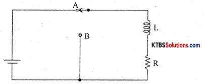
Consider an inductor Land a resistor R connected in series to a cell. When the switch is in position A, the current in the circuit grows exponentially.
The current I at a time after the switch is placed in position A is I = I0e-(R/L)t, where I0 is the maximum current.
The time constant of RL circuits is the time taken by the current to grow to 63.2% of the maximum value.
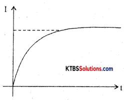
Growth of current in RL circuit
Question 36.
Explain V-I characteristics of a p-n junction diode.
Answer:
The V-I characteristic of a diode is the graph between the voltage across the diode and the current flowing through it.
The V-I characteristics can be divided into two parts namely
- Forward characteristics
- Reverse characteristics.
1. Forward characteristics of semiconductor diode:
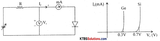
The circuit for plotting V-I characteristics of a diode is as shown. The resistance R limits the current to a permissible value. The voltmeter measures the voltage across the diode and the milliammeter reads the current flowing through the diode.
The forward voltage V is increased in steps of 0.1 V and the corresponding forward current VF is noted. A graph of VF along the x-axis and corresponding VF along the y-axis gives the forward characteristics curve.
Diode current VF is zero when VF = 0. When VF, is more than barrier potential, current ‘F increases. The forward voltage VF at which forward current starts to increase rapidly is called the knee voltage or cut-in voltage or threshold voltage (VK). For germanium diode, VK 0.3 V and for silicon diode, VK = 0.7V.
Reverse characteristics of an injunction:
The circuit for plotting reverse characteristics of a diode is shown below
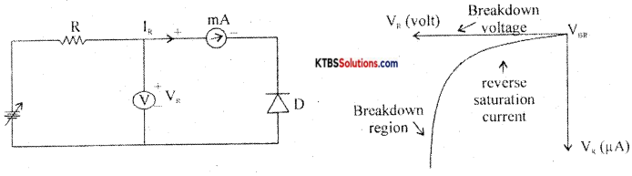
The reverse voltage is increased gradually till the diode starts conducting and the corresponding reverse currents are noted. On platting a graph between reverse voltage and reverse current, the characteristic curve is as shown.
Due to reverse bias applied on the p-n junction, an extremely small current I (few μA) flows through the diode. The reverse current remains almost constant up to the breakdown voltage.
After this point, for a small change in reverse voltage, the reverse current increases very rapidly. This sudden flow of large current may destroy the diode due to overheating. Hence, the diode should be operated in the reverse bias with reverse voltage less than break down voltage.
Question 37.
State and prove De-Morgans theorems.
Answer:
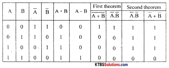
First theorem: The complement of a logical sum is equal to the logical product of complements
\(\overline{\mathrm{A}+\mathrm{B}}\) = A̅.B̅
Second theorem: The complement of a logical product is equal to the logical sum of complements.
\(\overline{\mathrm{AB}}\) = A̅ + B̅
Proof: